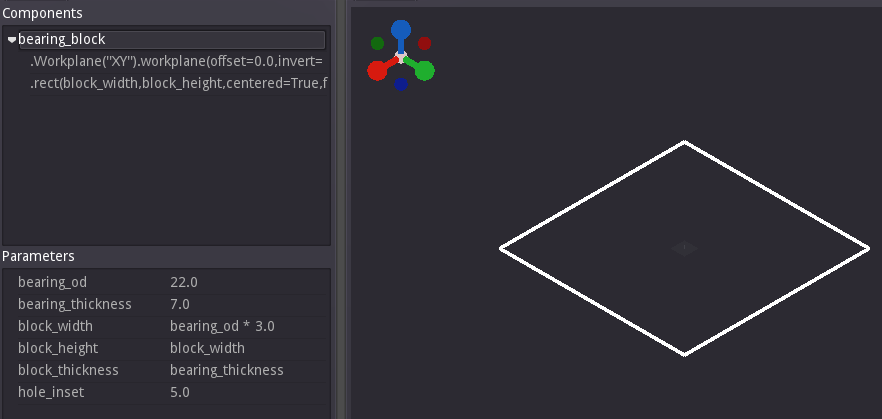
Bearing Block Tutorial
This is a good beginner tutorial which demonstrates some of the core concepts involved in creating a component with Semblage. It covers selectors, 2D sketching, and 3D operations such as extrusion and holes. Almost all controls have built-in documentation in the form of tooltips. To see the tooltip and get more information about a control, hover over the control with the mouse cursor.
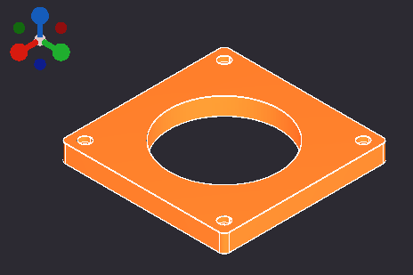
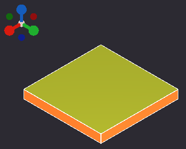
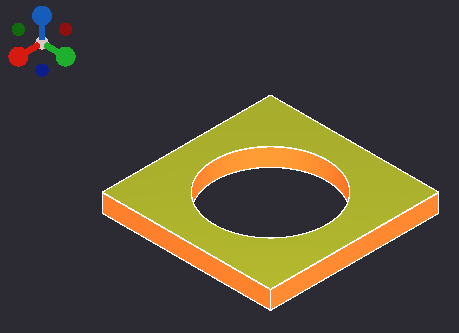
When finished, the bearing block that you create in this tutorial should look like this.
Defining Parameters
Parameters are what make a design "parametric", and we will put some thought into what parameters our design might have. How you set up parameters is highly dependent on the situation, but in general, it is ideal to set up a few core parameters and derive all other parameters from those, if possible. We are creating a bearing block in this example and the dimension that is fixed is that of the center hole for the bearing. Assuming that we do not have to match the hole pattern on a mating part, the bearing OD (outside diameter) can drive the rest of the design.
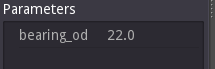
Step 1 - Add the Bearing OD Parameter
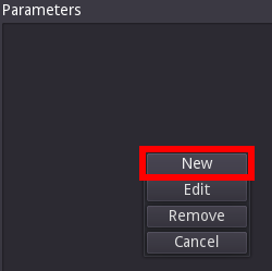
For the example we will design around a 608 ball bearing, which has a diameter of 22 mm and a thickness of 7 mm. First, add a parameter for the bearing diameter by right-clicking in a blank area of the Parameters list, and then clicking the New button.
This will display the Add/Edit Parameter dialog which has Name, Value, Type, and Comment controls for the new parameter. A detailed description of what each of these controls does is available in the Usage guide under the Add/Edit Parameter Dialog section.
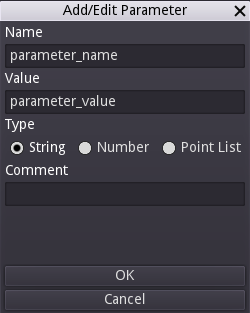
There are default placeholders in each field that must be changed. For the first parameter Name enter bearing_od to denote that the parameter is for the bearing outside diameter. You must follow the naming convention of not starting a variable with a number, and only using letters, numbers and underscores in your parameter name. Otherwise an error message will be displayed when you click the OK button. This is because the parameter name must also be a valid Python variable name for the underlying CadQuery script to be executed correctly.
Below the Value field is a set of Type controls. The parameter being created is a float value, so select Number. The Comment can be left blank for now, but is a field used for describing what a parameter is used for.
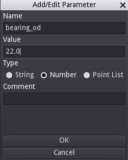
Now the value of 22.0 can be filled in for the Value field. If the Value is set before the Type is selected, the number will be reverted to 0.0.
The Add/Edit Parameter dialog should now look like this.
Click the OK button and the parameter will be added to the Parameters list in the main window.
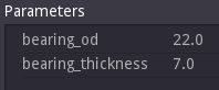
Step 2 - Add the Bearing Thickness Parameter
Repeat the process from step 1 by adding a parameter for the bearing thickness, using bearing_thickness as the Name, and 7.0 as the Value. After clicking the OK button, the Parameters list should look like this.
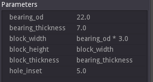
Step 3 - Add Derived Parameters
Formulas are allowed as parameter values, so it is possible to base one parameter on the value of another. This makes it possible to define relationships between different aspects of a design so that the entire design (or at least most of it) updates properly when a change is made. Determining the right parameters and creating good relationships between them for an optimal design can be hard, and takes practice and experimentation.
It is possible to over-do parameterization of your models, and so care should be taken to ensure that all parameters that are created add value to the end design. In this case, we are going to add parameters to determine the dimensions of the bearing block and the inset of the mounting hole pattern. A few more parameters could be added, but in an effort to keep this tutorial simpler they are omitted.
The width and height of the bearing block will be determined by the bearing size, and how much material there should be around the bearing to properly support a press fit. We will make our bearing block square, and the bearing will be flush with the top and bottom of the plate when pressed in. To achieve this, the following parameters need to be added.
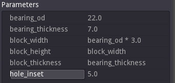
| Name | Value | Notes |
|---|---|---|
| block_width | bearing_od * 3.0 | 3.0 is arbitrary |
| block_height | block_width | So that height and width can be decoupled later |
| block_thickness | bearing_thickness | Extra thickness could be added later |
| hole_inset | 5.0 | Arbitrary, could be based on hole size too |
Once finished, the Parameters list should look like this.
Base Block
With the parameters set, we can now create a simple block for the main body of the bearing block.
Step 1 - Creating the Component
Right click on the 3D view to bring up the Operations dialog.
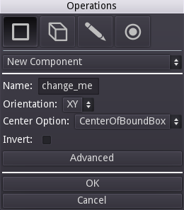
- Make sure that the first drop down shows
New Component, which should be the default. Every component design starts with a component object which has a base workplane that everything else is built on. - The Name field shows
change_me. This should be set to a meaningful and concise name for the component, such asbearing_block. Note that component names need to follow the same naming conventions as parameters so that they can be used as CadQuery variable names. - The Orientation drop down sets the axes that define the component's base workplane. For instance, XY sets the workplane to be aligned with both the X and Y axes.
XYis a safe choice for many desktop manufacturing uses because the bed of a 3D printer or CNC router is typically defined as the X and Y axes, and the print head (or spindle) is the Z or "up" axis. We will build the bearing plate "up" the Z axis, much like a 3D printer would print it. - Center Option - This option can get a little complicated, but for now the default of
CenterOfBoundBoxwill work fine. This defines the center of the workplane as being the geometric center of the component. The other center options have nuances that we won't cover here. - Invert - This defines whether the normal, or "up", direction from the workplane is in a positive or negative direction. The default is unchecked, which works well for our purposes and means that the normal will be in the positive direction.
- Advanced - This button shows another set of controls that allow a user to define a workplane in whatever location and orientation they choose. For our purposes, this is not needed.
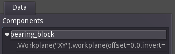
With the Name field set to bearing_block and the other controls left at their defaults, click the OK button. At this point you should have a semi-transparent representation of the workplane that was just created. If you rotate the view, you will see that there is a plane representing the workplane, and a spike which represents the normal of the workplane. The normal can become important in certain operations like when doing a cut or creating a hole.

You will also notice that a bearing_block entry has been added to the Components list of the main user interface, with a workplane creation operation attached to it. You do not need to understand the workplane operation at this point, Semblage just provides access to it if you ever want or need to interact more directly with the CadQuery object underneath.
Step 2 - Creating a 2D Sketch on the Workplane
Now that there is a workplane to place geometry on, it is time to create the 2D sketch that will become the base block. Right click to bring up the Operations dialog again, and click the 2D button at the top (pencil icon).
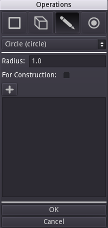
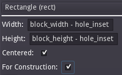
By default, the circle operation will be selected. In this case we want to create a rect (rectangle). Click on the operation dropdown at the top of the dialog that says Circle (circle), find Rectangle (rect), and click it. The rect controls should load and the dialog should look like the following.
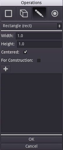
It is time to define the attributes of the rectangle based on the parameters we set up earlier.
- Change the Width value to
block_width. This is the width of the rectangle. - Change the Height value to
block_height. This is the height of the rectangle. - Leave Centered checked. When an object is centered, it will have the origin of (0, 0) directly at its center. It is a nice way to keep your component neatly centered around the origin of the workplane.
- Leave For Construction unchecked. This option is not needed now, but will be used in a later step.
If the rect controls look as they do in the following screenshot, go ahead and click the OK button.
At this point a 2D representation of the rectangle should be visible in the 3D view, and the rect operation will show up in the Components tree under the component you created previously. The 2D rectangle sketch will be used in the next operation.
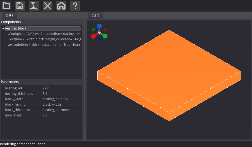
Step 3 - Extrude the Rectangle
The next operation will be extrude. Right click on the 3D view again to bring the Operations dialog back up. Click on the 3D button. In most cases this button will be selected by default once a workplane has been created.
Click on the operation drop down at the top of the dialog, select Extrude (extrude) from the list, and then set the Distance to block_thickness as shown below.
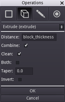
Below is an explanation to each of the extrude settings.
- Distance - The distance that the extrude operation will move through. This will determine the depth dimension of the resulting solid.
- Combine - Determines whether or not this resulting solid should be combined with other existing solids within this component.
- Clean - When set, will ask the CAD kernel to clean the resulting solid(s). By default this is checked, and can be unchecked if an extrude results in an invalid solid due to a CAD kernel issue.
- Both - Will cause the extrude operation to move through the specified distance in both the positive and negative normal directions at the same time.
- Taper - Causes the extruded area to increase or decrease as the extrude moves over the distance. A positive taper will cause the area to decrease and a negative taper will cause the area to increase.
- Invert - Checking this will cause the extrusion to move in the opposite direction from the workplane normal.
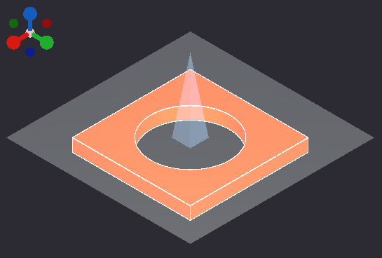
Once the extrude settings are as shown, click the OK button. The result should look something like this in the main window.
Center Hole
The center hole that the bearing presses into can now be added. To tell Semblage (and by extension CadQuery) which face to place the next feature on, we use selectors. Selectors are a flexible way to capture design intent. For instance, if we select the face in the maximum Z axis direction, the furthest face will always be selected, even if steps or other features are added to the component. Selectors help make designs less brittle.
In Semblage, faces can be selected by holding the Shift key and clicking on them with the left mouse button.
Step 1 - Select a Face to Place a Circle On
The hole in the center of the block runs through the Z axis. We could choose either to start the hole from the minimum Z or maximum Z sides of the block, but starting from the maximum Z direction feels a little bit more like a drilling operation in a CNC mill, so we will do that.
While holding down the Shift key, left click on the top-most face in the Z direction, as shown in the following screenshot.
Continue holding the Shift key and right click on the 3D view to bring up the Operations dialog. The Selectors tab should be set to active, and the Face selector field should show an auto-generated selector string for the face you selected.
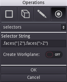
We want to add a hole to the selected face, and so we will tell Semblage to create a workplane on that face by toggling the Create Workplane control to ON. The rest of the controls that appear when the workplane control is toggled can be left at their defaults.
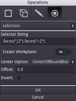
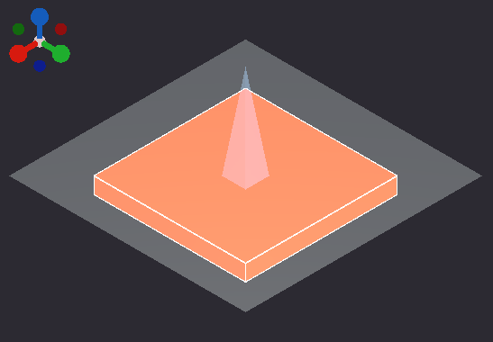
Click OK to add this selector to the Components tree. The original block will be shown with a translucent workplane visualization on the topmost face.
Step 2 - Add the Hole Circle
Now that the "top" face of the block has been selected and has a workplane, we can place a circle the size of the center hole on it and cut it through the block. We could also just add a 3D hole operation, but the idea with this tutorial is to follow the workflow of 2D sketch -> 3D operation as much as possible. As you gain more experience with Semblage and CadQuery, you will start to use orders of operations that feel right for you in a given situation, even if they deviate from this standard workflow.
Bring up the Operations dialog (right click), and follow these steps.
- Click the 2D sketch mode button
- The
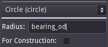
circleoperation should be shown by default, but if it is not, click the operation drop down and select it - Set the value of Radius to
bearing_od, which is the parameter we set before. - Leave For Construction unchecked
The circle controls in the dialog should now look like this.
Note that in most cases a press-fit tolerance would be added to the hole to make sure the bearing fits correctly. To keep things a little simpler, we have omitted that here.
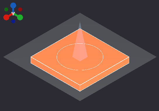
Click the OK button to add the circle to the component. The circle will be displayed on the selector workplane in the 3D view at this point.
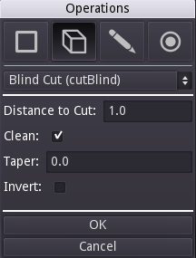
Step 3 - Add the Cut Operation
With the circle placed, a cut operation can now be added. Open the Operations dialog with a right click again, and perform the following steps.
- Click the 3D button to select the group of 3D operations.
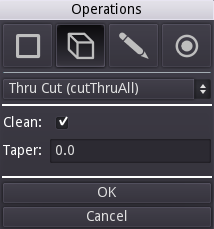
- Click the operation drop down and select
Thru Cut (cutThruAll)from the list. We do a thru cut because if we created a blind cut with a distance, and then changed the thickness of the plate, the hole might not go all the way through the plate anymore. UsingcutThruAllensures that our design intent is preserved, even when the component changes. - All of the default
cutThruAlloptions are what we need for this. If you need a tapered hole, the Taper option could be used, but we do not need that in this case
The Operations dialog should now look like the following.
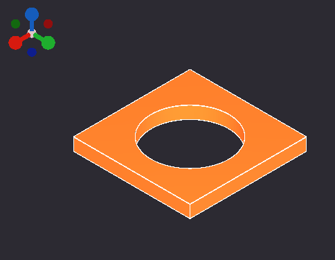
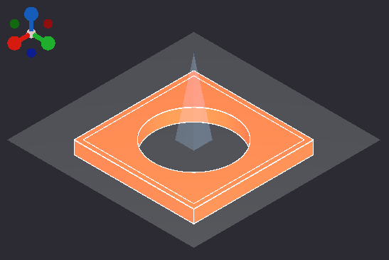
Click the OK button when all settings match the screenshot. This adds the cutThruAll operation to the component and the resulting render is shown in the screenshot below.
Counter-bore Mounting Holes
We now want to place counter-bore holes in each of the 4 corners of the block. We are going to place another rectangle on the maximum Z ("top") surface of the block, but this time we are going to make it construction geometry. This type of geometry is used only for placing other geometry and features, not for being converted into a solid by a 3D operation.
Step 1 - Set Location of Construction Geometry
We need to select the face that the construction geometry will be placed on. As with the center hole, mimicking a machining operation and starting from the maximum "top" Z surface can be a good default.
While holding down the Shift key, left click on the top-most face in the Z direction, as shown in the following screenshot.
Continue holding the Shift key and right click on the 3D view to bring up the Operations dialog. The Selectors tab should be set to active, and the Face selector field should show an auto-generated selector string for the face you selected.
We want to add a hole to the selected face, and so we will tell Semblage to create a workplane on that face by toggling the Create Workplane control to ON. The rest of the controls that appear when the workplane control is toggled can be left at their defaults.
Click OK to add this selector to the Components tree. The original block will be shown with a translucent workplane visualization on the topmost face.
Step 2 - Add Construction Rectangle
Next we will add the rectangle that will be used to place the holes. Right click to bring the Operations dialog back up, then follow these steps.
- Click the Sketch mode button to select the group of 2D operation controls.
- Click the operation drop down and select
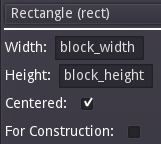
Rectangle (rect). - Set the Width value to
block_width - hole_inset, which insets the rectangle from the edge of the block along the width dimension. - Set the Height value to
block_height - hole_inset, which insets the rectangle from the edge of the block along the height dimension. - Leave Centered checked. We centered the rectangle that was used to build the base block, and so we want to center this one as well.
- Check the box next to For Construction. This is what determines that the rectangle will only be used to place other geometry.
The rect controls should now look like the following screenshot.
Click the OK button to add the construction rectangle to the component. The rectangle will be shown on top of the bearing block in the 3D view, inset from the outer edge.
Step 4 - Select Rectangle Vertices to Place Holes
With the construction rectangle now available, we can select the vertices in each of the 4 corners and use those to place the counter-bore holes. There is no selector generation for vertices yet, so this must be done manually. Bring up the Operations dialog again and follow these steps.
- Click the Selectors mode button.
- In the Selector String field, enter
.vertices(). This will select all the vertices of the construction rectangle, which effectively selects all the corners. - Leave the Create Workplane toggle on OFF since we do not want to place workplanes on the vertices, we only want to use them to locate the holes in the next operation.
The Operations dialog should now look like this.
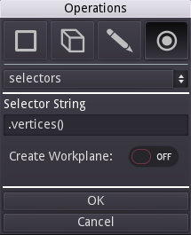
Click OK to add the selector to the component. Vertex selector visualizations have not been implemented yet, and so a plain visualization of the bearing block will be shown. However, a .vertices() entry will be shown in the Components tree indicating that the selector was successful.
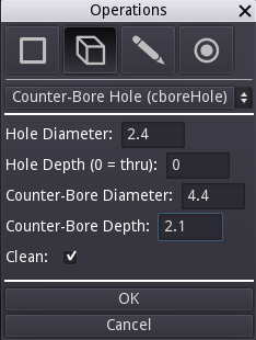
Step 3 - Add Counter-Bore Holes
With the construction rectangle vertices selected, we can use those to place the counter-bore holes. The dimensions for the holes are set based on an M2 socket-head cap screw. Bring up the Operations dialog again and follow these steps.
- Make sure that 3D mode is selected.
- Click the operation drop down and select
Counter-Bore Hole (cboreHole). - Set Hole Diameter to
2.4. - Leave Hole Depth at
0for thru. - Set Counter-Bore Diameter to
4.4. - Set Counter-Bore Depth to
2.1. - Leave Clean checked.
The Operations dialog should now look like this.
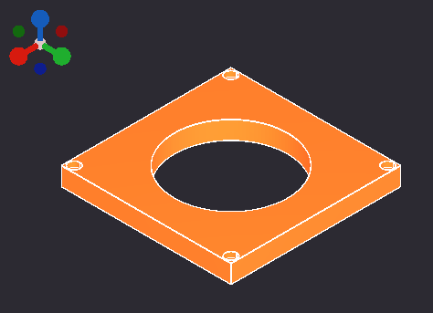
Click the OK button to add the counter-bore holes to the block. The bearing block should now look like the following.
Adjust A Parameter
Notice that the counter-bore holes are too close to the edge of the block. This is easy to fix since we tied the hole positions to the hole_inset parameter. Follow these steps to update the hole locations.
- Double click the
hole_insetparameter in the Parameters list. Alternatively, right-click on thehole_insetparameter and then click theEditbutton.
Double clicking the parameter will bring up the Add/Edit Parameter dialog. Note that it is not possible to edit the parameter name in this dialog. To rename a parameter, you must delete and recreate it.
2.Change the hole_inset parameter to 10. The parameter dialog should now look like this.
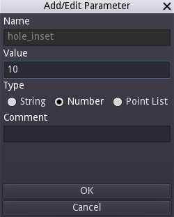
Click the OK button to update the parameter and re-render the bearing block. The block should now look like this.
Fillet Corners
The last thing to do is to break the corner edges on the block with fillets. We only want to fillet the edges that are parallel to the Z axis, so we will use a new selector for those.
Step 1 - Select the Edges
While holding down the Shift key, left click on one of the corner edges that are aligned with the Z direction, as shown in the following screenshot.

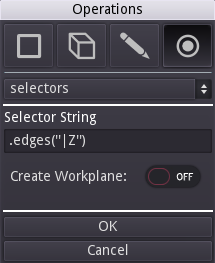
Continue holding the Shift key and right click on the 3D view to bring up the Operations dialog. The Selectors tab should be set to active, and the Selector String field should show an auto-generated selector string for the edge you selected. The Operations dialog should now look like this.
Click the OK button to add the edge selector to the component. Only the bearing block will be displayed. Edge selector visualization is planned for the future.
Step 2 - Apply the Fillets
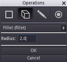
The last thing to do is to fillet the edges that have been selected. Open the Operations dialog and follow these steps.
- Click the 3D mode button.
- Click the operation drop down and select
Fillet (fillet). - There is only one setting for the fillet command, and that is Radius. Set that to
2.0.
The dialog should look like this now.
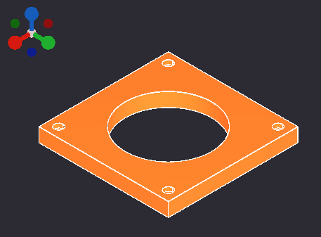
Click the OK button to add the fillet to the component. The final bearing block should render and look like this.
Extra Credit
There are other things that can be done with this bearing block, and improvements are left as an exercise for the reader. Here are some ideas.
- Change the counter-bore hole inset based on bolt size (M2 vs M5).
- Add a boss for the bearing to press into instead of having it be flush with the plate.
- Change the
block_widthandblock_heightparameters to round to the nearest 10 to keep dimensions nice and even. Keep in mind that underneath everything, Semblage is just executing a Python script, and so all the rules that apply to Python can apply to your parameters (which are just Python variables).
Finished
That is it, you have finished your first Semblage tutorial. More tutorials will be added in the future, but for now, please try Semblage out and feel free to ask questions or make comments on the community channels.